This note applies to all Red Lion N-Tron NT24K series Managed switches
Summary
If connected to a Layer 3 switch or router that is set up for multiple subnets through VLAN, then it will be necessary to configure those VLANs on the networks managed switches. These VLANs can be used in conjunction with the Layer 3 device to perform Inter-VLAN Routing if needed.
This example would apply for any switch to switch connection to a VLAN Trunk. A Layer 3 switch is being used in this example.
10.10.20.101 is directly connected to the Layer 3 switch VLAN trunk port on port 3 for VLANs 301 and 48. Access ports were created for each VLAN on the Layer 3 switch. These screen captures are managing the switches through the Layer 3 switch.
In the VLAN configuration view there is a checkbox to remove ports from the default VLAN when added to other vlans. Before starting click modify and uncheck this box so you can control this manually. Be sure that the check box to change the PVID member ports is unchecked. It is better to set the PVIDs manually in the port configuration view.
VLAN 48 was created on 10.10.20.101 and ports 3 and 8 are members. This is so it will carry the VLAN tag when it comes in. There is no need to have the PVID 48 on a port since the VLAN is not used on this switch. Creating the VLAN and adding the network Ports while unchecking untag on egress lets it pass without stripping the Tag.
The default VLAN 1 is used as a catch all to get the traffic around the switch (and serves as a VLAN trunk). It is internal to the switch if set properly. As a security best practice, the PVID 1 should only be used on switch to switch connections.
To prevent being locked out of the switch when you create the VLANs you may want to keep your pc connection out of the VLANs (Do not remove the port from the default VLAN 1 or change the PVID) until you are done. Once it works through the Layer 3 Switch you can change the PVID to whatever the access VLAN is. Uncheck the remove ports from default VLAN so you can manipulate the PVID
s yourself
10.10.10.101 is connected to 10.10.20.102 on port 3. Port 8 would be for another network connection.
NOTE:
The NT24K switch does not have a VLAN trunk function. The Trunk function in the NT24K switch is used for link aggregation. We will use VLAN 1 as a catch all VLAN to be used like a VLAN trunk to carry all VLANs on the switch to switch connection. The switch to switch (or network) port should be in each VLAN that you want to be passed to the other switches. The default VLAN is important to the operation of the N-Tron switch. It should be left alone unless policy dictates that VLAN 1 is not used on the network. This example does not cover that scenario.
Untag on egress – strips the VLAN tag on outgoing traffic.
Uncheck untag on egress – retains the tag that was on the frame as it leaves the port
Configuration
Switch 10.10.20.101
Step 1
On the VLAN Configuration View, Click Modify
Click Add under VLAN Groups
Step 2
In the Tagged VLAN group configuration, enter the VLAN ID (PVID) and Name. Be sure to uncheck "Change PVID of member ports" so that we can manually enter them later.
Uncheck "Remove Ports From Default VLAN When Added To This VLAN"
Create VLAN 48
Create VLAN 301
Under the Port Configuration View, change the PVID of the ports in each VLAN. End device ports should have a new PVID, and Switch to Switch ports will keep the PVID 1
Set the PVID in the PVID drop down box.
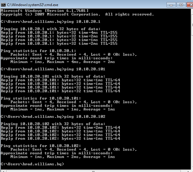
To test the configuration of switch 10.10.10.20.101, ping the gateway, switch, and PC's on the subnet 10.10.20.0 255.255.255.0 from the PC connected to the Layer 3 switch.
Switch 10.10.10.101
Repeat Step 1 above on switch 10.10.10.101.
Step 2
Create the VLANs on the 10.10.10.101 switch.
VLAN 48
VLAN 301
Set the PVIDs for Switch 10.10.10.101
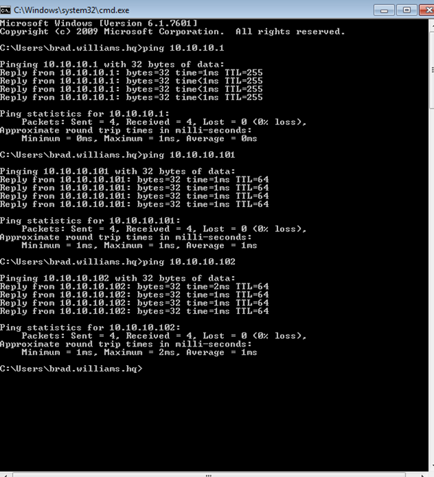
To test the configuration of switch 10.10.10.10.101, ping the gateway, switch, and PC's on the subnet 10.10.10.0 255.255.255.0 from the PC connected to the Layer 3 switch.
Topology
For reference, the port and VLAN configuration from the Layer 3 switch is below.
interface FastEthernet0/1
switchport access vlan 48
switchport mode access
spanning-tree portfast
!
interface FastEthernet0/2
switchport access vlan 301
switchport mode access
spanning-tree portfast
!
interface FastEthernet0/12
switchport trunk encapsulation dot1q
switchport trunk allowed vlan 48,301
switchport mode trunk
!
interface Vlan48
ip address 10.10.10.1 255.255.255.0
!
interface Vlan301
ip address 10.10.20.1 255.255.255.0
It is the customer's responsibility to review the advice provided herein and its applicability to the system. Red Lion makes no representation about specific knowledge of the customer's system or the specific performance of the system. Red Lion is not responsible for any damage to equipment or connected systems. The use of this document is at your own risk. Red Lion standard product warranty applies.
If you have any questions or trouble contact Red Lion Technical Support by clicking here or calling 1-877-432-9908.
For more information: http://www.redlion.net/support/policies-statements/warranty-statement